

The technical notes organized by subject below are currently available online. For TechNotes not listed here, contact us and we'll mail or fax a paper copy.
If you know the number of the technical note you need, use the link in the column at right to find it quickly.
Subject categories
| Fittings | TN no. | Rev | |
|---|---|---|---|
| Cheminert fittings |
Cheminert connecting accessories
(Use of the flanging tool) How to use a flanging tool to install Cheminert tube end fittings on PTFE tubing |
TN 502
How to use a flanging tool to install Cheminert tube end fittings on PTFE tubing
|
3/01 |
|
Flangeless fittings with collapsible ferrule
Instructions for installing Cheminert flangeless fittings with CTFE or PEEK one-piece collapsible ferrules.
|
TN 505a
Instructions for installing Cheminert flangeless fittings with CTFE or PEEK one-piece collapsible ferrules.
|
10/03 | |
|
Nanovolume one-piece 1/32" fittings,
installation and use Nanovolume1/32" fittings incorporate a grooved ferrule designed to break away from the nut as the ferrule starts to grip the tubing. |
TN 507
Nanovolume1/32" fittings incorporate a grooved ferrule designed to break away from the nut as the ferrule starts to grip the tubing.
|
12/01 | |
|
Cheminert 360 micron fittings,
installation and use Cheminert high pressure 360 micron fittings, consisting of a nut with snap-in ferrule, permit direct connection of 360 micron OD stainless, PEEK, fused silica, or electroformed nickel tubing. |
TN 509
Cheminert high pressure 360 micron fittings, consisting of a nut with snap-in ferrule, permit direct connection of 360 micron OD stainless, PEEK, fused silica, or electroformed nickel tubing.
|
9/17 | |
|
360µm to 1/16" fitting (C360IZR1)
The Cheminert C360IZR1 connects a 360 µm fused silica tube directly into a 1/16" fitting detail.
|
TN 512
The Cheminert C360IZR1 connects a 360 µm fused silica tube directly into a 1/16" fitting detail.
|
10/18 | |
| Valco fittings |
EZR and IZR installation instructions
EZRs adapt an external tee or union or Parker and Swagelok® type fittings to Valco ZDV connections. IZRs are most commonly used for adapting small transfer lines to Valco valves with larger fittings.
|
TN 504
EZRs adapt an external tee or union or Parker and Swagelok® type fittings to Valco ZDV connections. IZRs are most commonly used for adapting small transfer lines to Valco valves with larger fittings.
|
6/14 |
|
Fused silica adapters,
installation and use
Valco fused silica adapters permit easy use of open tubular columns with Valco valves, and provide direct connection of fused silica within Valco fittings for maximum bore uniformity and inertness.
|
TN 501
Valco fused silica adapters permit easy use of open tubular columns with Valco valves, and provide direct connection of fused silica within Valco fittings for maximum bore uniformity and inertness.
|
10/07 | |
|
IZERA1.5 installation instructions
Valco IZERA1.5 and IZERA1.5M fittings are unique 1/16" internal to 1/32" external adapters, designed to eliminate graphite ferrules getting stuck in 1/32" internal fitting details. A typical application is the connection of a fused silica capillary to a valve or detector.
|
TN 506
Valco IZERA1.5 and IZERA1.5M fittings are unique 1/16" internal to 1/32" external adapters, designed to eliminate graphite ferrules getting stuck in 1/32" internal fitting details. A typical application is the connection of a fused silica capillary to a valve or detector.
|
9/00 | |
|
Zero dead volume (ZDV) fitting instructions
Since leak-tightness and integrity of the fitting are dependent upon tubing preparation and proper assembly, this publication addresses those two topics.
|
TN 503
Since leak-tightness and integrity of the fitting are dependent upon tubing preparation and proper assembly, this publication addresses those two topics.
|
11/06 | |
|
Zero dead volume fill port fittings
How to use the Valco ZVISF-1, a unique fill port fitting designed so that the required leaktight seal is formed against the face of the bottom of the fitting detail instead of at the end of an angular ferrule.
|
TN 510
How to use the Valco ZVISF-1, a unique fill port fitting designed so that the required leaktight seal is formed against the face of the bottom of the fitting detail instead of at the end of an angular ferrule.
|
9/12 | |
Subject categories
| Fused Silica Tube Preparation | TN no. | Rev |
|---|---|---|
|
Lapping the ends of fused silica tubing
Normal methods of cutting fused silica leave a high spot, which can cause problems in applications requiring minimal dead volume. The VICI Fused Silica Prep kit includes everything needed to polish the burred end into a clean, perfectly square-cut surface.
|
TN 621
Normal methods of cutting fused silica leave a high spot, which can cause problems in applications requiring minimal dead volume. The VICI Fused Silica Prep kit includes everything needed to polish the burred end into a clean, perfectly square-cut surface.
|
6/18 |
Subject categories
| TN no. | Rev | |
|---|---|---|
|
Cleaning or Replacing a Pulsed Discharge Detector Ground Pin
Detector sensitivity can often be restored by removing and cleaning the ground pin; however, in some cases the ground pin must be replaced.
|
TN 620
Detector sensitivity can often be restored by removing and cleaning the ground pin; however, in some cases the ground pin must be replaced.
|
9/18 |
Subject categories
| Purge housing | TN no. | Rev |
|---|---|---|
|
Two position and multiposition valves
Describes how to remove the valve from the purge housing for cleaning or shaft and seal replacement.
|
TN 602
Describes how to remove the valve from the purge housing for cleaning or shaft and seal replacement.
|
4/06 |
Subject categories
| Heated valve enclosures | TN no. | Rev |
|---|---|---|
|
Installing a valve
(single valve model)
Models HVEA, HVEB, or HVEC
|
TN 601
Models HVEA, HVEB, or HVEC
|
9/00 |
|
Installing a valve
(two or three valve model)
Models HVE2 or HVE3
|
TN 604
Models HVE2 or HVE3
|
4/01 |
Subject categories
| Flow controllers | TN no. | Rev |
|---|---|---|
|
Model 100
upstream-referenced fixed span flow controller
Covers specifications, dimensions, and flow rates and characteristics.
|
TN 613
Covers specifications, dimensions, and flow rates and characteristics.
|
1/11 |
|
Model 202
upstream-referenced adjustable span flow controller
Covers specifications, dimensions, flow rate setting, and flow characteristics.
|
TN 614
Covers specifications, dimensions, flow rate setting, and flow characteristics.
|
11/17 |
|
Model 300
downstream-referenced fixed span flow controller
Covers specifications, dimensions, and flow rates and characteristics.
|
TN 615
Covers specifications, dimensions, and flow rates and characteristics.
|
1/11 |
|
Dial mounting instructions (from the dial manufacturer's site)
Also includes dimensional drawings
|
-- |
Subject categories
| VCom software | TN no. | Rev |
|---|---|---|
|
User guide
How to select a serial port, create a new method file, open and edit a file, and run a method.
|
TN 618
How to select a serial port, create a new method file, open and edit a file, and run a method.
|
7/12 |
Subject categories
| Cheminert valves | TN no. | Rev | ||
|---|---|---|---|---|
| General information |
Cheminert UHPLC Valves and Selectors
Notice of design change Details design changes made in July of 2015 |
TN 827
Details design changes made in July of 2015
|
7/15 | |
|
Cheminert UHPLC Valves and Selectors
Notice of rotor material change Details change from Valcon E3 to Valcon E5 made in the first quarter of 2020 |
TN 829
Details change from Valcon E3 to Valcon E5 made in the first quarter of 2020
|
12/19 | ||
| Cleaning and rotor replacement |
Cheminert HPLC and UHPLC injectors
Includes initial precautions and instructions for disassembly, cleaning, inspecting, and reassembling.
|
TN 801
Includes initial precautions and instructions for disassembly, cleaning, inspecting, and reassembling.
|
12/14 | |
|
Nanovolume® models CN2 and CN4
Includes initial precautions and instructions for disassembly, cleaning, inspecting, and reassembling.
|
TN 813
Includes initial precautions and instructions for disassembly, cleaning, inspecting, and reassembling.
|
12/14 | ||
|
Models C22, C24, C25, C22Z, C24Z, and C25Z
Includes initial precautions and instructions for disassembly, cleaning, inspecting, and reassembling.
|
TN 811
Includes initial precautions and instructions for disassembly, cleaning, inspecting, and reassembling.
|
12/14 | ||
|
Models C35Z and (obsolete) C45
Includes initial precautions and instructions for disassembly, cleaning, inspecting, and reassembling. Also includes alignment instructions for the C35Z.
|
TN 816
Includes initial precautions and instructions for disassembly, cleaning, inspecting, and reassembling. Also includes alignment instructions for the C35Z.
|
12/01 | ||
|
Model C42R
Includes initial precautions and instructions for disassembly, cleaning, inspecting, and reassembling.
|
TN 828
Includes initial precautions and instructions for disassembly, cleaning, inspecting, and reassembling.
|
2/16 | ||
|
Model C45R
Includes initial precautions and instructions for disassembly, cleaning, inspecting, and reassembling.
|
TN 826
Includes initial precautions and instructions for disassembly, cleaning, inspecting, and reassembling.
|
1/15 | ||
| Installation, use, and maintenance |
Models C1 and C1CF
Includes information about panel mounting, connecting the fittings, sample loading, and position feedback, as well as instructions for disassembly, cleaning, inspecting, and reassembling.
|
TN 802
Includes information about panel mounting, connecting the fittings, sample loading, and position feedback, as well as instructions for disassembly, cleaning, inspecting, and reassembling.
|
9/19 | |
|
Model C25G
Includes initial precautions and instructions for disassembly, cleaning, inspecting, and reassembling. Also has instructions for the special 6-40 fittings.
|
TN 824
Includes initial precautions and instructions for disassembly, cleaning, inspecting, and reassembling. Also has instructions for the special 6-40 fittings.
|
1/15 | ||
|
Models C52, C62, and C62Z
Includes initial precautions and instructions for disassembly, cleaning, inspecting, and reassembling. Also details about dimensions, electrical connections, motor control modes, and optional serial control.
|
TN 819
Includes initial precautions and instructions for disassembly, cleaning, inspecting, and reassembling. Also details about dimensions, electrical connections, motor control modes, and optional serial control.
|
6/20 | ||
|
Models C55, C65, and C65Z
Includes initial precautions and instructions for disassembly, cleaning, inspecting, and reassembling. Also details about dimensions, electrical connections, motor control modes, and optional serial control.
|
TN 821
Includes initial precautions and instructions for disassembly, cleaning, inspecting, and reassembling. Also details about dimensions, electrical connections, motor control modes, and optional serial control.
|
6/20 | ||
|
Selectors, air- and
electrically-actuated
Includes initial precautions and instructions for disassembly, cleaning, inspecting, and reassembling. Also how to implement their use on air and standard electric actuators, including alignment instructions.
|
TN 814
Includes initial precautions and instructions for disassembly, cleaning, inspecting, and reassembling. Also how to implement their use on air and standard electric actuators, including alignment instructions.
|
4/14 | ||
|
Loop fill port assembly
Installation and use, including mounting the valve and installing the tubing.
|
TN 806
Installation and use, including mounting the valve and installing the tubing.
|
9/00 | ||
| Flow diagrams |
4 port |
Internal sample (fixed volume) injector
Schematic flow diagram
|
TN 807
Schematic flow diagram
|
11/07 |
|
Switching valve
Schematic flow diagram
|
TN 803
Schematic flow diagram
|
11/07 | ||
| 6 port |
External volume sample injector
Schematic flow diagram
|
TN 808
Schematic flow diagram
|
8/11 | |
|
Model C3 external volume sample injector
Schematic flow diagram
|
TN 808b
Schematic flow diagram
|
10/00 | ||
|
Model C6 continuous flow injector
Schematic flow diagram
|
TN 820
Schematic flow diagram
|
12/18 | ||
| 8 port |
External volume sample injector
Schematic flow diagram
|
TN 809
Schematic flow diagram
|
11/07 | |
| 10 port |
Switching valve
Schematic flow diagram
|
TN 810
Schematic flow diagram
|
11/07 | |
| Stream selector |
Model C5F
Schematic flow diagram
|
TN 815
Schematic flow diagram
|
7/13 | |
|
Model C35ZF
Schematic flow diagram
|
TN 822
Schematic flow diagram
|
9/09 | ||
|
Model C35ZT
Schematic flow diagram
|
TN 823
Schematic flow diagram
|
9/09 | ||
Subject categories
| Diaphragm valves | TN no. | Rev | |
|---|---|---|---|
| Operation instructions |
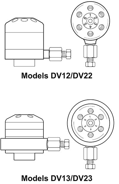
Models DV-12 and DV-22
Instructions for installation and operation.
|
TN 605
Instructions for installation and operation.
|
7/20 |
|
Models DV-13 and DV-23
Instructions for installation and operation.
|
TN 622
Instructions for installation and operation.
|
7/20 | |
| Diaphragm replacement |
Models DV-12 and DV-22
How to install a replacement diaphragm.
|
TN 606
How to install a replacement diaphragm.
|
9/12 |
|
Models DV-13 and DV-23
How to install a replacement diaphragm.
|
TN 623
How to install a replacement diaphragm.
|
7/20 | |
Subject categories
| Valco valves | TN no. | Rev | |||
|---|---|---|---|---|---|
| General information |
Installing a loop
General instructions for loop installation on a C6W.
|
TN 105
General instructions for loop installation on a C6W.
|
9/00 | ||
|
Installing a microvolume loop
(20 µl or less)
Tips for installing the smallest-volume loops (shortest length of tubing) on C6Ws.
|
TN 104
Tips for installing the smallest-volume loops (shortest length of tubing) on C6Ws.
|
9/00 | |||
|
Internally purged valves
Valco internally purged two position and selector models have additional ports for a purge gas as well as O-ring seals on the rotor and driver to eliminate any possible diffusion from the atmosphere into the valve, or to safely vent fugitive emissions from the valve.
|
TN 107
Valco internally purged two position and selector models have additional ports for a purge gas as well as O-ring seals on the rotor and driver to eliminate any possible diffusion from the atmosphere into the valve, or to safely vent fugitive emissions from the valve.
|
10/13 | |||
| Two position |
Operating notes and
cleaning instructions
Includes initial precautions and instructions for disassembly, cleaning, inspecting, and reassembling. Also details conditioning procedure for high temperature valves and special instructions for high pressure W and UW valves.
|
TN 201
Includes initial precautions and instructions for disassembly, cleaning, inspecting, and reassembling. Also details conditioning procedure for high temperature valves and special instructions for high pressure W and UW valves.
|
12/18 | ||
|
Valve alignment troubleshooting
Causes and symptoms of misalignment between a 2 position valve and actuator, and a procedure to restore proper alignment.
|
TN 101
Causes and symptoms of misalignment between a 2 position valve and actuator, and a procedure to restore proper alignment.
|
2/10 | |||
|
Mounting 10 port W valves
Discusses breakthrough of threads into mounting holes, old and new design.
|
TN 103
Discusses breakthrough of threads into mounting holes, old and new design.
|
12/09 | |||
|
Manual feedback assembly – W valves
The PFW, comprising a knob with a socket head set screw and a bearing plate with a contact and signal cable, provides position feedback for two position manually-actuated valves in the form of a permanent contact closure for TTL logic signals at Position B.
|
TN 106
The PFW, comprising a knob with a socket head set screw and a bearing plate with a contact and signal cable, provides position feedback for two position manually-actuated valves in the form of a permanent contact closure for TTL logic signals at Position B.
|
7/13 | |||
|
Dual internal volume injector
Special instructions for W and UW internal volume sample injectors with two sample sizes – how to rotate the rotor to change the sample size, and how the sample slots are oriented relative to the rotor tab and rotor polymer ID letter.
|
TN 208
Special instructions for W and UW internal volume sample injectors with two sample sizes – how to rotate the rotor to change the sample size, and how the sample slots are oriented relative to the rotor tab and rotor polymer ID letter.
|
9/00 | |||
| Flow diagrams |
3 port |
Switching valve
Schematic flow diagram
|
TN 207
Schematic flow diagram
|
10/00 | |
| 4 port |
Internal volume sample injector
Schematic flow diagram
|
TN 202
Schematic flow diagram
|
10/00 | ||
|
Switching valve
Schematic flow diagram
|
TN 206
Schematic flow diagram
|
10/00 | |||
| 6 port |
External volume sample injector
Schematic flow diagram
|
TN 203
Schematic flow diagram
|
10/00 | ||
| 8 port |
External volume sample injector
Schematic flow diagram
|
TN 204
Schematic flow diagram
|
10/00 | ||
| 10 port |
Multifunctional valve
Schematic flow diagram
|
TN 205
Schematic flow diagram
|
10/00 | ||
| Selectors | Flow diagrams |
Dead-end Flowpath:
SD configuration Schematic flow diagram |
TN 710
Schematic flow diagram
|
9/15 | |
|
Common Outlet Flowpath:
SC configuration Schematic flow diagram |
TN 711
Schematic flow diagram
|
9/15 | |||
|
Flow-through Flowpath:
SF configuration Schematic flow diagram |
TN 712
Schematic flow diagram
|
9/15 | |||
|
Trapping Flowpath:
ST configuration Schematic flow diagram |
TN 713
Schematic flow diagram
|
9/15 | |||
|
Trapping/Flow-through Flowpath:
STF configuration Schematic flow diagram |
TN 714
Schematic flow diagram
|
9/15 | |||
| Cleaning, rotor replacement, and alignment instructions |
UW and MW valves on microelectric and universal actuators (keyed hardware)
Includes alignment instructions for UW and MW valves on microelectric and universal actuators with keyed hardware.
|
TN 715
Includes alignment instructions for UW and MW valves on microelectric and universal actuators with keyed hardware.
|
7/17 | ||
| Alignment instructions for selector valves with legacy unkeyed mounting hardware |
MW valves on air actuators
For selector valves with legacy unkeyed mounting hardware.
|
TN 707
For selector valves with legacy unkeyed mounting hardware.
|
12/00 | ||
|
MW valves on standard electric actuators
For selector valves with legacy unkeyed mounting hardware.
|
TN 708
For selector valves with legacy unkeyed mounting hardware.
|
7/17 | |||
|
UW valves on air actuators
For selector valves with legacy unkeyed mounting hardware.
|
TN 705
For selector valves with legacy unkeyed mounting hardware.
|
12/00 | |||
|
UW valves on standard electrical actuators
For selector valves with legacy unkeyed mounting hardware.
|
TN 706
For selector valves with legacy unkeyed mounting hardware.
|
7/17 | |||
| Cleaning and rotor replacement |
High temperature valves
Includes alignment instructions for legacy unkeyed mounting hardware.
|
TN 704
Includes alignment instructions for legacy unkeyed mounting hardware.
|
4/17 | ||
|
Low temperature valves
Includes alignment instructions for legacy unkeyed mounting hardware.
|
TN 703
Includes alignment instructions for legacy unkeyed mounting hardware.
|
4/17 | |||
|
Actuator considerations
for Valco column selectors CST4UW and CST6UW valves
These two products are the exceptions to the rule that the number of positions of the actuator is indicated by the product number.
|
TN 709
These two products are the exceptions to the rule that the number of positions of the actuator is indicated by the product number.
|
7/05 | |||
Subject categories
| Older Valco valves with visible coil spring | TN no. | Rev | |
|---|---|---|---|
| Operation notes and cleaning instructions |
P and E Series valves
Includes initial precautions and instructions for disassembly, cleaning, inspecting, and reassembling.
|
TN 304
Includes initial precautions and instructions for disassembly, cleaning, inspecting, and reassembling.
|
10/00 |
|
P and E Series VL type valves
Includes initial precautions and instructions for disassembly, cleaning, inspecting, and reassembling.
|
TN 310
Includes initial precautions and instructions for disassembly, cleaning, inspecting, and reassembling.
|
10/00 | |
|
T Series valves
Includes initial precautions and instructions for disassembly, cleaning, inspecting, and reassembling. Also details conditioning procedure for high temperature valves.
|
TN 305
Includes initial precautions and instructions for disassembly, cleaning, inspecting, and reassembling. Also details conditioning procedure for high temperature valves.
|
10/00 | |
| Operation notes and cleaning and alignment instructions, multiposition valves |
High temperature valves
Includes alignment instructions for legacy unkeyed mounting hardware.
|
TN 704
Includes alignment instructions for legacy unkeyed mounting hardware.
|
4/17 |
|
Low temperature valves
Includes alignment instructions for legacy unkeyed mounting hardware.
|
TN 703
Includes alignment instructions for legacy unkeyed mounting hardware.
|
4/17 | |
| Flow diagrams |
3 port switching valve
Schematic flow diagram
|
TN 307
Schematic flow diagram
|
10/00 |
|
4 port internal sample injector
Schematic flow diagram
|
TN 301
Schematic flow diagram
|
10/00 | |
|
4 port switching valve
Schematic flow diagram
|
TN 306
Schematic flow diagram
|
10/00 | |
|
6 port sample injector
Schematic flow diagram
|
TN 302
Schematic flow diagram
|
10/00 | |
|
8 port switching valve
Schematic flow diagram
|
TN 303
Schematic flow diagram
|
10/00 | |
|
10 port multifunctional valve
Schematic flow diagram
|
TN 308
Schematic flow diagram
|
10/00 | |
|
10 port internal sample injector
Schematic flow diagram
|
TN 309
Schematic flow diagram
|
10/00 | |
Subject categories
| Micrometering (needle) valves | TN no. | Rev |
|---|---|---|
|
Mounting instructions
How to mount a BNV1 or ZBNV1, and how to replace a screen in a ZBNV1.
|
TN 603
How to mount a BNV1 or ZBNV1, and how to replace a screen in a ZBNV1.
|
5/18 |
Subject categories
| Standard on-off and prime-purge valves | TN no. | Rev | |
|---|---|---|---|
| On-off valves |
Air actuated, installation and use
Describes the various configurations available, and offers instructions for mounting and actuation.
|
TN 607
Describes the various configurations available, and offers instructions for mounting and actuation.
|
6/14 |
|
Manually operated, installation and use
Describes the various configurations available, and offers instructions for mounting and actuation.
|
TN 609
Describes the various configurations available, and offers instructions for mounting and actuation.
|
7/14 | |
| Prime-purge valves |
Air actuated, installation and use
Describes the various configurations available, and offers instructions for mounting and actuation.
|
TN 608
Describes the various configurations available, and offers instructions for mounting and actuation.
|
7/14 |
|
Manually operated, installation and use
Describes the various configurations available, and offers instructions for mounting and actuation.
|
TN 610
Describes the various configurations available, and offers instructions for mounting and actuation.
|
11/03 | |
| 40K psi on-off and prime-purge valves | TN no. | Rev | |
|---|---|---|---|
| On-off valves |
Installation and use
Describes the various configurations available, and offers instructions for mounting and actuation.
|
TN 616
Describes the various configurations available, and offers instructions for mounting and actuation.
|
12/11 |
Subject categories
| Valve actuation | TN no. | Rev | ||
|---|---|---|---|---|
| Air actuators | Two position |
Implementation - older solenoids
Using a pair 3-way solenoid valves (MSVA) to apply air to the actuator only during switching, alleviating problems associated with continous air pressure. Also describes an alternate method using a single 41E1 4-way solenoid. (Not recommended.)
|
TN 405
Using a pair 3-way solenoid valves (MSVA) to apply air to the actuator only during switching, alleviating problems associated with continous air pressure. Also describes an alternate method using a single 41E1 4-way solenoid. (Not recommended.)
|
7/18 |
|
Implementation - current solenoids
Using a pair 3-way solenoid valves (Model 310 or MSVA2) to apply air to the actuator only during switching, alleviating problems associated with continous air pressure. Also describes and alternate method using a single 4-way solenoid. (Model 410 or V-SV-S52) (Not recommended.)
|
TN 425
Using a pair 3-way solenoid valves (Model 310 or MSVA2) to apply air to the actuator only during switching, alleviating problems associated with continous air pressure. Also describes and alternate method using a single 4-way solenoid. (Model 410 or V-SV-S52) (Not recommended.)
|
7/18 | ||
|
O-ring replacement
How to install O-ring kit OR or ORT to repair a leaking actuator.
|
TN 409
How to install O-ring kit OR or ORT to repair a leaking actuator.
|
3/20 | ||
|
Digital Valve Interface (DVI)
implementaion
Installing a DVI – an electronic controller which converts low power logic level signals or contact closures into pneumatic pulses for the operation of Valco two position air actuated valves.
|
TN 411
Installing a DVI – an electronic controller which converts low power logic level signals or contact closures into pneumatic pulses for the operation of Valco two position air actuated valves.
|
9/04 | ||
|
High Speed Switching Accessory (HSSA)
implementation
The high speed switching accessory (HSSA) provides increased air or helium flow for the fast actuation required in partial loop injections or microbore chromatography.
|
TN 412
The high speed switching accessory (HSSA) provides increased air or helium flow for the fast actuation required in partial loop injections or microbore chromatography.
|
1/00 | ||
|
Position Feedback (PFAF)
implementation
The PFAF can be installed on any VICI two position air actuator (30° - 90°). In each position, the PFAF offers a permanent contact closure for TTL logic signals.
|
TN 419
The PFAF can be installed on any VICI two position air actuator (30° - 90°). In each position, the PFAF offers a permanent contact closure for TTL logic signals.
|
6/08 | ||
| Multiposition |
Implementation - older solenoids
Use of a 4-way solenoid (41E1 or 41E1-CE) is recommended for multiposition actuators. In this implementation air is continuously applied to the actuator, which is directed to step or reset by the solenoid.
|
TN 406
Use of a 4-way solenoid (41E1 or 41E1-CE) is recommended for multiposition actuators. In this implementation air is continuously applied to the actuator, which is directed to step or reset by the solenoid.
|
7/18 | |
|
Implementation - current solenoids
Use of a 4-way solenoid (Model 410 or V-SV-S52) is recommended for multiposition actuators. In this implementation air is continuously applied to the actuator, which is directed to step or reset by the solenoid.
|
TN 426
Use of a 4-way solenoid (Model 410 or V-SV-S52) is recommended for multiposition actuators. In this implementation air is continuously applied to the actuator, which is directed to step or reset by the solenoid.
|
7/18 | ||
|
O-ring replacement
How to install O-ring kit ORMP or ORTMP to repair a leaking actuator.
|
TN 410
How to install O-ring kit ORMP or ORTMP to repair a leaking actuator.
|
3/20 | ||
|
Multiposition air actuator position indicator switch
Installation of a position indicator switch, typically used to supply inputs to a digital system or to power an LED readout requiring a maximum of 0.5 amps at 28 VDC.
|
TN 430
Installation of a position indicator switch, typically used to supply inputs to a digital system or to power an LED readout requiring a maximum of 0.5 amps at 28 VDC.
|
5/18 | ||
| Universal actuator |
Models EUH, EUD, and EUT
Covers mounting and dimensions, cabling, and control via the standard interface or optional serial or BCD interface.
|
Manual
Covers mounting and dimensions, cabling, and control via the standard interface or optional serial or BCD interface.
|
8/18 | |
|
USB tutorial part 1: Downloading the USB drivers
If you are proficient at downloading and installing drivers in a Windows environment, go directly to part 3, "Verifying Actuator Communication."
|
TN 420-1
If you are proficient at downloading and installing drivers in a Windows environment, go directly to part 3, "Verifying Actuator Communication."
|
3/11 | ||
|
USB tutorial part 2: Installing the USB drivers
If you are proficient at downloading and installing drivers in a Windows environment, go directly to part 3, "Verifying Actuator Communication."
|
TN 420-2
If you are proficient at downloading and installing drivers in a Windows environment, go directly to part 3, "Verifying Actuator Communication."
|
3/11 | ||
|
USB tutorial part 3: Verifying actuator communication
Step-by-step instructions for establishing and verifying serial communication.
|
TN 420-3
Step-by-step instructions for establishing and verifying serial communication.
|
3/11 | ||
|
Universal Actuator and Power Supply Assembly
Cable PN I-25418 must be inserted between the universal actuator assembly and the power supply.
|
TN 427
Cable PN I-25418 must be inserted between the universal actuator assembly and the power supply.
|
11/13 | ||
|
Using Valco Electric Actuators with Sciex Analyst® Software
Sciex Analyst LC-MS/MS acquisition software for TripleQuad and QTRAP instruments is fully compatible with Valco two-position microelectric actuators. Also explains how to use universal actuators in legacy mode.
|
TN 428
Sciex Analyst LC-MS/MS acquisition software for TripleQuad and QTRAP instruments is fully compatible with Valco two-position microelectric actuators. Also explains how to use universal actuators in legacy mode.
|
10/20 | ||
|
Setting a Universal Actuator for Operation in Legacy Mode
The universal actuator in its legacy mode emulates the behavior and responses of microelectric actuators. This allows them to be used with lab software products designed to incorporate VICI microelectric actuators, but not the newer VICI universal actuators.
|
TN 429
The universal actuator in its legacy mode emulates the behavior and responses of microelectric actuators. This allows them to be used with lab software products designed to incorporate VICI microelectric actuators, but not the newer VICI universal actuators.
|
6/16 | ||
|
Universal Acuator: BCD Connection to an Agilent 8890 GC
Describes the cabling required, and proper connection and configuration.
|
TN 436
Describes the cabling required, and proper connection and configuration.
|
12/20 | ||
| Modular Universal | ||||
| 9/22 | ||||
| 9/22 | ||||
| Microelectric actuators |
Two position |
EM2C controller, installation and use (EM2C controller was obsoleted in 2010; newer models refer to TN 421)
Includes descriptions of cable and connector functions, mounting instructions, and how to control the actuator digitally or through a serial interface.
|
TN 413
Includes descriptions of cable and connector functions, mounting instructions, and how to control the actuator digitally or through a serial interface.
|
8/18 |
|
E2CA controller, installation and use
Includes descriptions of cable and connector functions, mounting instructions, and how to control the actuator digitally or through a serial interface.
|
TN 421
Includes descriptions of cable and connector functions, mounting instructions, and how to control the actuator digitally or through a serial interface.
|
8/18 | ||
|
EM2C, forced initialization procedure
How to reinitialize a Valco microelectric actuator after the valve has been loosened or removed, or when the actuator controller has been replaced.
|
TN 413a
How to reinitialize a Valco microelectric actuator after the valve has been loosened or removed, or when the actuator controller has been replaced.
|
5/05 | ||
|
Using Valco Electric Actuators with Sciex Analyst® Software
Sciex Analyst LC-MS/MS acquisition software for TripleQuad and QTRAP instruments is fully compatible with Valco two-position microelectric actuators. Also explains how to use universal actuators in legacy mode.
|
TN 428
Sciex Analyst LC-MS/MS acquisition software for TripleQuad and QTRAP instruments is fully compatible with Valco two-position microelectric actuators. Also explains how to use universal actuators in legacy mode.
|
6/16 | ||
| Multiposition |
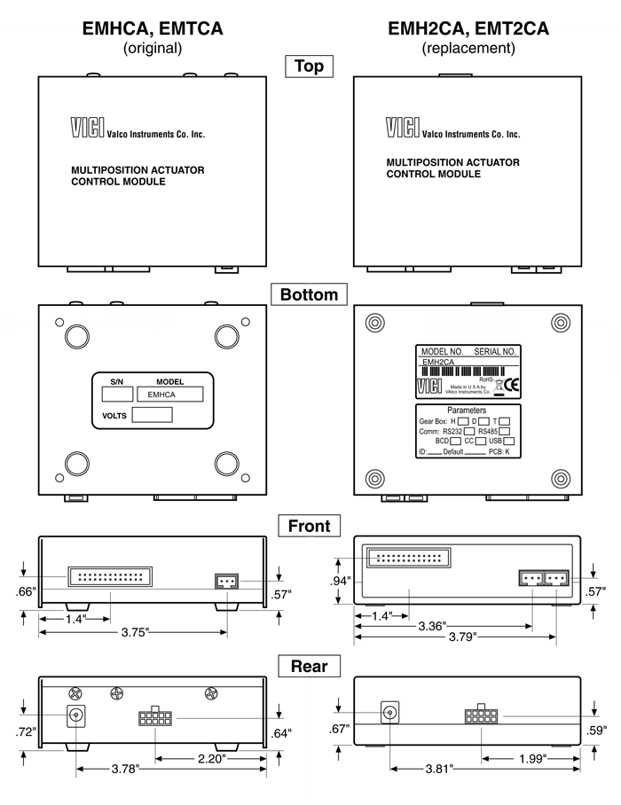
EMHCA or EMTCA, installation and use (EMHCA and EMTCA controllers were obsoleted in January of 2019; newer models refer to TN 435)
Includes descriptions of cable and connector functions, mounting instructions, and how to control the actuator with the manual controller, or via digital or serial control.
|
TN 415
Includes descriptions of cable and connector functions, mounting instructions, and how to control the actuator with the manual controller, or via digital or serial control.
|
8/18 | |
|
Quick start guide
Includes descriptions of cable and connector functions, mounting instructions, and how to control the actuator with the manual controller. Also a basic method of control via an external system.
|
TN 415QS
Includes descriptions of cable and connector functions, mounting instructions, and how to control the actuator with the manual controller. Also a basic method of control via an external system.
|
10/14 | ||
|
Change Summary: Multiposition microelectric actuator controller
Description of changes to the multiposition microelectric actuator controller, as well as the purpose and the effects.
|
TN 434
Description of changes to the multiposition microelectric actuator controller, as well as the purpose and the effects.
|
12/18 | ||
| Illustration comparing new and old controllers | ||||
|
EMH2CA or EMT2CA, installation and use
Includes descriptions of cable and connector functions, mounting instructions, and how to control the actuator with the manual controller, or via digital or serial control.
|
TN 435
Includes descriptions of cable and connector functions, mounting instructions, and how to control the actuator with the manual controller, or via digital or serial control.
|
3/19 | ||
|
Quick start guide
Includes descriptions of cable and connector functions, mounting instructions, and how to control the actuator with the manual controller. Also a basic method of control via an external system.
|
TN 435QS
Includes descriptions of cable and connector functions, mounting instructions, and how to control the actuator with the manual controller. Also a basic method of control via an external system.
|
3/19 | ||
| Standard electric actuators (Obsolete) |
Two position |
Installation and use
General description plus how to control with the manual controller, or automated control by a data system capable of generating contact closure or negative true logic level signals.
|
TN 417
General description plus how to control with the manual controller, or automated control by a data system capable of generating contact closure or negative true logic level signals.
|
11/00 |
|
Modifications
How to make fine adjustments to the stroke distance, or change it to work with a valve with a different number of ports of positions.
|
Manual
How to make fine adjustments to the stroke distance, or change it to work with a valve with a different number of ports of positions.
|
10/10 | ||
| Multiposition |
Installation and use
General description plus how to control with the manual controller, or automated control by a data system capable of generating contact closure or negative true logic level signals.
|
TN 418
General description plus how to control with the manual controller, or automated control by a data system capable of generating contact closure or negative true logic level signals.
|
8/07 | |
|
Modifications
How to make fine adjustments to the stroke distance, or change it to work with a valve with a different number of ports of positions.
|
Manual
How to make fine adjustments to the stroke distance, or change it to work with a valve with a different number of ports of positions.
|
1/06 | ||
| Closemount hardware |
For air or electric actuators
How to remove the valve and mounting hardware from the actuator and put it back together with proper alignment between valve and actuator.
|
TN 403
How to remove the valve and mounting hardware from the actuator and put it back together with proper alignment between valve and actuator.
|
2/10 | |
|
Manual actuation assembly for two position W and UW valves
How to remove or install the closemount manual hardware on a Valco two position W or UW valve.
|
TN 401
How to remove or install the closemount manual hardware on a Valco two position W or UW valve.
|
9/00 | ||
|
Installing a Cheminert Selector on a Clamp Ring
A few simple tips can help you avoid any problems or damage when reinstalling a valve on an actuator.
|
TN 422
A few simple tips can help you avoid any problems or damage when reinstalling a valve on an actuator.
|
9/10 | ||
| Standoff assemblies |
For air or electric actuators
Includes instructions about installing the valve/actuator/standoff assembly on an instrument. Also shows how to separate the valve, standoff, and actuator and get it all back together with proper alignment between valve and actuator.
|
TN 404
Includes instructions about installing the valve/actuator/standoff assembly on an instrument. Also shows how to separate the valve, standoff, and actuator and get it all back together with proper alignment between valve and actuator.
|
3/03 | |
|
For manual actuation
How to remove or install a standoff and handle or knob.
|
TN 402
How to remove or install a standoff and handle or knob.
|
12/18 | ||
| Clamp rings |
Descriptions and Applications
Illustrations, dimensions, and functions of the various VICI clamp rings.
|
TN 431
Illustrations, dimensions, and functions of the various VICI clamp rings.
|
9/18 | |
|
Rheodyne adapter kit installation instructions
The Rheodyne adapter kit (RAK) permits a Rheodyne HPLC injector (Series 7000-9000) to be installed on a Valco two position microelectric actuator.
|
TN 416
The Rheodyne adapter kit (RAK) permits a Rheodyne HPLC injector (Series 7000-9000) to be installed on a Valco two position microelectric actuator.
|
9/06 | ||